Circular-Layout Reference
Light-weight drawing of nodes and edges in a circular layout
1 Overview
A lightweight Racket module which draws a graph of nodes and edges in a circular layout, as an alternative to more powerful graph-rendering e.g. graphviz.
Nodes are defined using make-cl-node (which sets a name, size, a label and color), and edges are defined using make-cl-edge (which defines the source and target nodes, the weight of the edge, a label, and whether the edge is directed, i.e. has an arrow). A list of these nodes and edges are passed to draw-circular-layout along with a destination drawing context ( dc<%>); scale factor and center of the graph within the drawing context also specified.
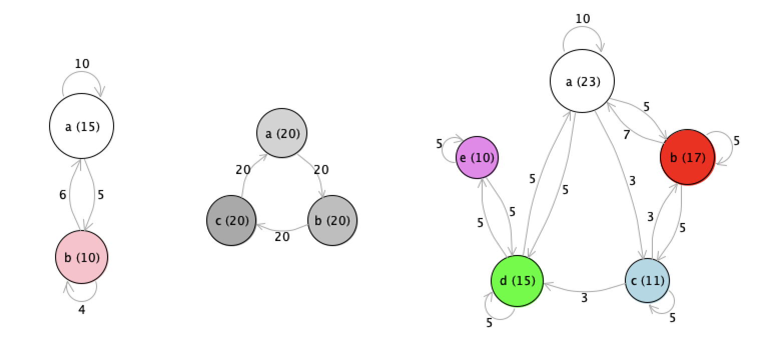
2 Example output
3 Example usage
#lang racket (require circular-layout) (require racket/gui/base) ;; a simple graph with 5 nodes and some edges (define nodes (list (clnode "a" 23 "a (23)" "white") (clnode "b" 17 "b (17)" "red") (clnode "c" 11 "c (11)" "lightblue") (clnode "d" 15 "d (15)" "green") (clnode "e" 10 "e (10)" "violet"))) (define edges (list (cledge "a" "a" 1 "10" #t) (cledge "a" "b" 1 "5" #t) (cledge "a" "c" 1 "3" #t) (cledge "a" "d" 1 "5" #t) (cledge "b" "a" 1 "7" #t) (cledge "b" "c" 1 "5" #t) (cledge "b" "b" 1 "5" #t) (cledge "c" "c" 1 "5" #t) (cledge "c" "b" 1 "3" #t) (cledge "c" "d" 1 "3" #t) (cledge "d" "d" 1 "5" #t) (cledge "d" "a" 1 "5" #t) (cledge "d" "e" 1 "5" #t) (cledge "e" "e" 1 "5" #t) (cledge "e" "d" 1 "5" #t))) ;; set up a drawing canvas with a bitmap, and an image-snip% to display in REPL (define target (make-bitmap 400 400)) (define dc (new bitmap-dc% [bitmap target])) (make-object image-snip% target) ;; call the circular-layout function to draw the graph (draw-circular-layout #:dc dc #:nodes nodes #:edges edges #:center '(200 . 200) #:scale 10)
4 Reference
| (require circular-layout) | package: circular-layout |
Added in version 1.0 of package circular-layout.
struct
(struct clnode (name size label color))
name : string? size : number? label : string? color : string?
name is the identifier of the node.
size determines the area of the node’s circle – in dc pixels, if scale = 1 – which is conserved in the area of the node’s circle.
label is the string drawn at the center of the node.
color is the string representation of the color used to fill the node.
struct
(struct cledge (source target width label directed))
source : string? target : string? width : number? label : string? directed : boolean?
source is the identifier of the source node, i.e, matches name of one of the clnodes in accompanying list of nodes.
target is the identifier of the target node, i.e., matches name of one of the clnodes in accompanying list of nodes. If source and target are the same name of a single node, then the edge is a self-edge from that node back to that same node.
width determines the pen-width of the edge line in pixels (regardless of scale).
label is the string drawn at the control point of the edge curve.
directed is a boolean flag that determines if an arrow is drawn pointing at target node (optional: defaults to #t).
procedure
(make-cl-node #:name name [ #:size size #:label label #:color color]) → clnode? name : string? size : number? = 1 label : (or/c #f string?) = #f color : string? = "white"
procedure
(make-cl-edge #:source source #:target target [ #:label label #:width width #:directed directed]) → cledge? source : string? target : string? label : string? = "" width : number? = 1 directed : boolean? = #t
procedure
(draw-circular-layout #:dc dc #:nodes nodes #:edges edges #:center center #:scale scale) → void? dc : (is-a?/c dc<%>) nodes : (listof clnode?) edges : (listof cledge?) center : (cons/c number? number?) scale : number?
5 To Do
Function to return bounds of rendered layout (so we can appropriately size bitmap to fit).
Needs improvements to labeling of nodes.
Parameterize some of the drawing constants to allow customization.